Worldwide express shipping
Worldwide express shipping

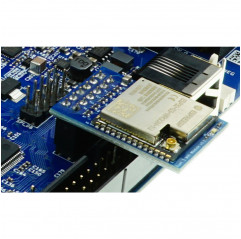
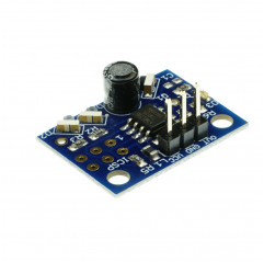
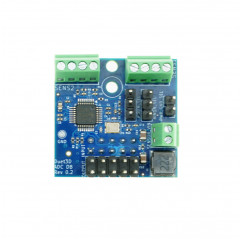
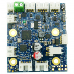
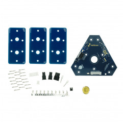
Duet 3 Expansion Mini 2XD is designed specifically for the Duet 3 Mini 5+ expansion connector. It can also be used with other boards, but such use is not officially supported. The board offers 2 channels driver for external motors, with specifications equivalent to those found on the Duet 3 6XD.
Hardware specifications
Operating limits.
Firmware Notes.
Compatible versions of RepRapFirmware: RRF 3.6.1 and later, when used on the Duet 3 Mini 5+ main board.
Earlier firmware versions can provide proper motion, but do not support DRIVER_ERROR inputs.
There is no firmware loaded directly on the Duet 3 Expansion Mini 2XD.
The driver are numbered as "5" and "6" to allow them to be referenced, for example, to assign them to the X and Y axes:
M584 X5 Y6
Use the M569 command to set the appropriate timing parameters for the external driver, for example:
M569 P5 T2:2:2
M569 P6 T2:2:2:2
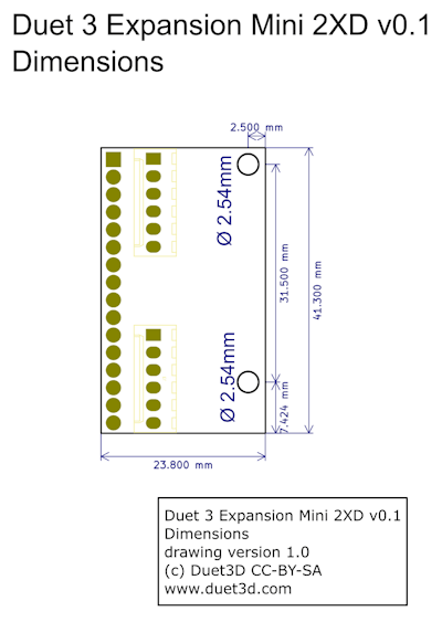
Dimensions
Mounting
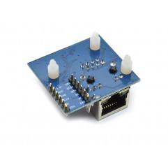
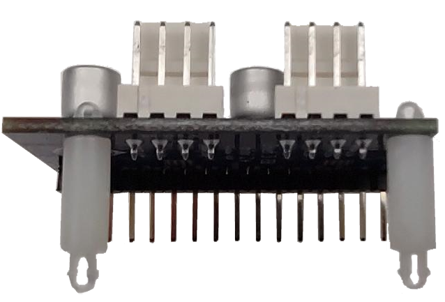
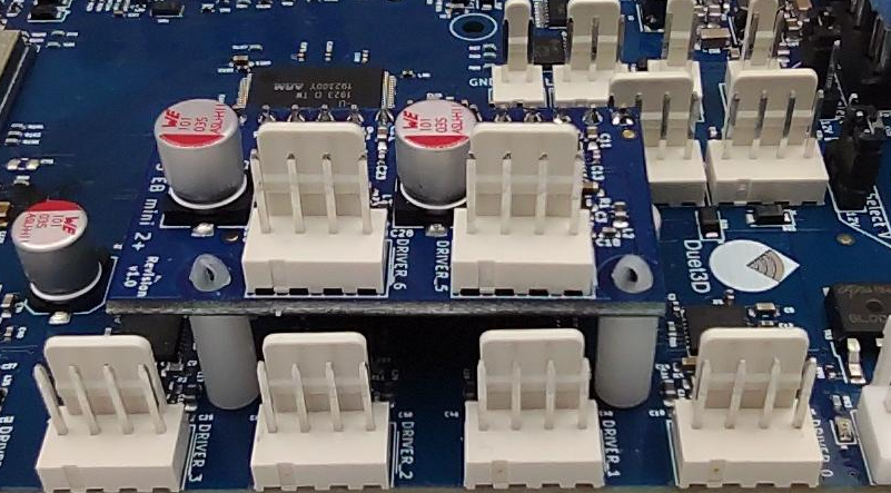
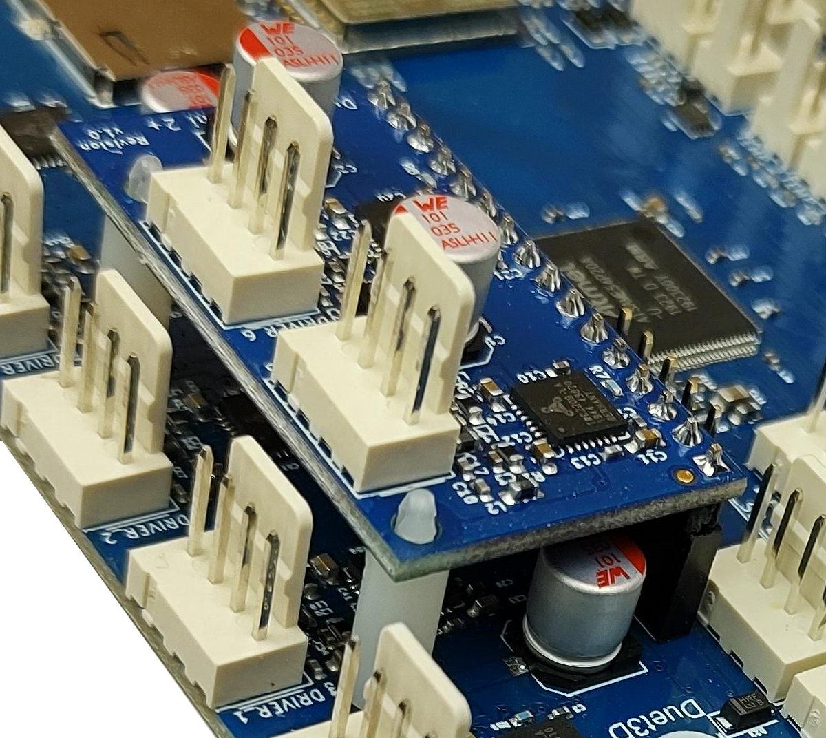
Duet 3 Expansion Mini 2XD has mounting holes with standoffs (standoff holes) that align with the corresponding holes on the Duet 3 Mini 5+. The pictures show the Mini 2+ board mounted, but the procedure is identical for the Mini 2XD. The Duet 3 Expansion Mini 2XD comes with nylon spacers, which are needed to securely fasten it. Spacer height: 11 mm Compatible with 1.6 mm PCB and 2.5 mm holes Examples of compatible spacers: FIX-MADA-11 or TRDLCBST-7-01
Wiring Diagram
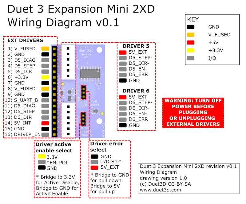
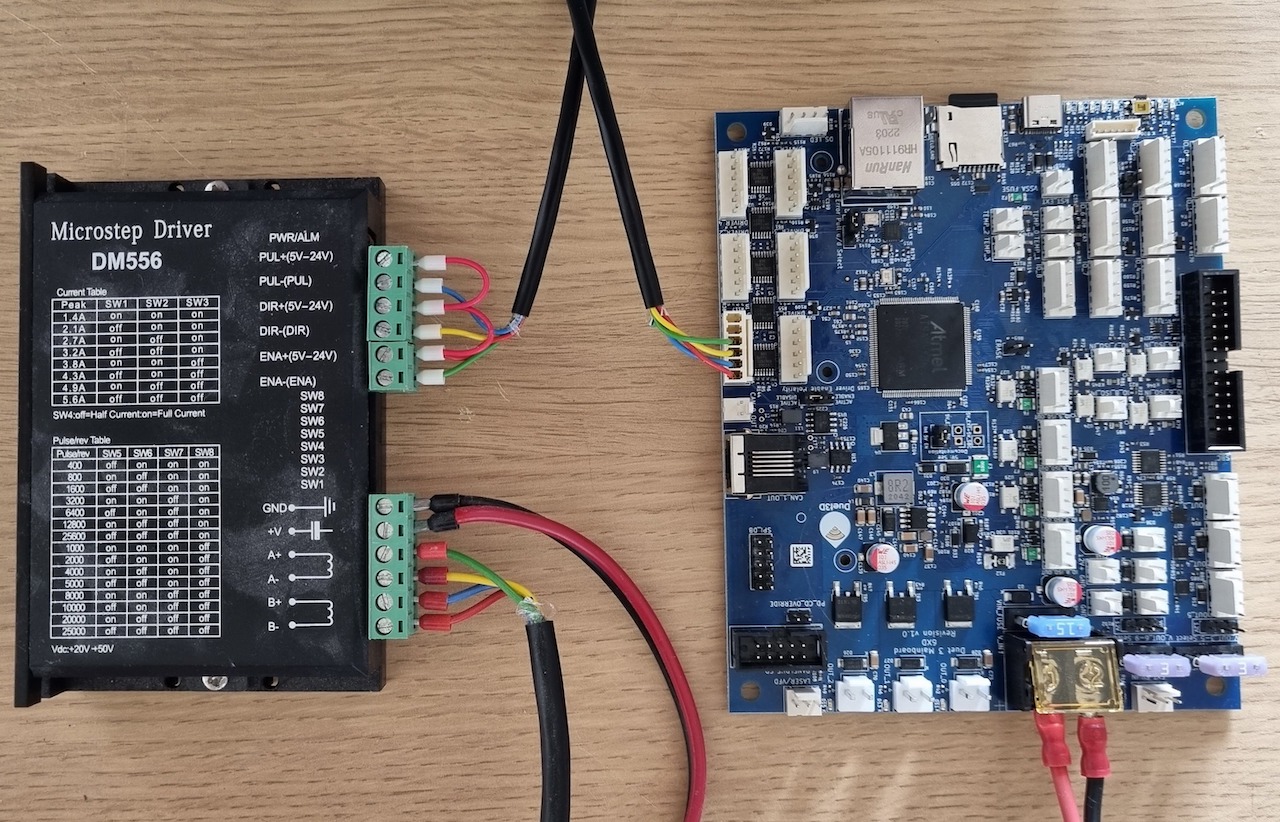
Connection of External Driver for Motors
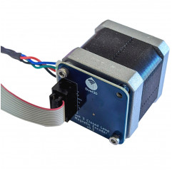
Duet 3 Expansion Mini 2XD supports the direct connection of driver external stepper motor drives equipped with opto-isolated inputs or equivalent.
Note that:
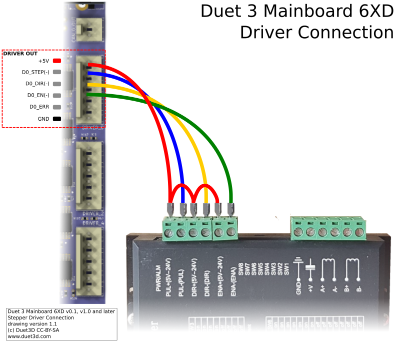
The following diagram shows the connection to a driver for typical opto-isolated stepper motor; the connection is identical to that of Duet 3 6XD.
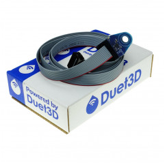
Package contains: 1 x Duet 3 Mini 2XD Expansion Board