€247.05Price
Worldwide express shipping
Worldwide express shipping

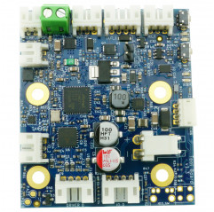
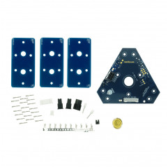
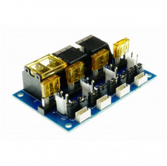
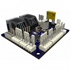
Duet 3 Tool Distribution Board is designed to simplify the connection of multiple Duet 3 Toolboards 1LC and/or Duet 3 Roto Toolboards to the Duet 3 CAN-FD bus by providing outputs for CAN and power supply, bus pass-through, and bus termination. A significant change was made between v0.5 and v1.0 to make wiring simpler, especially that of branches (stubs).
Key features
The Duet 3 Tool Distribution Board v1.0 comes with:
Operating limits
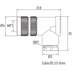
Dimensions

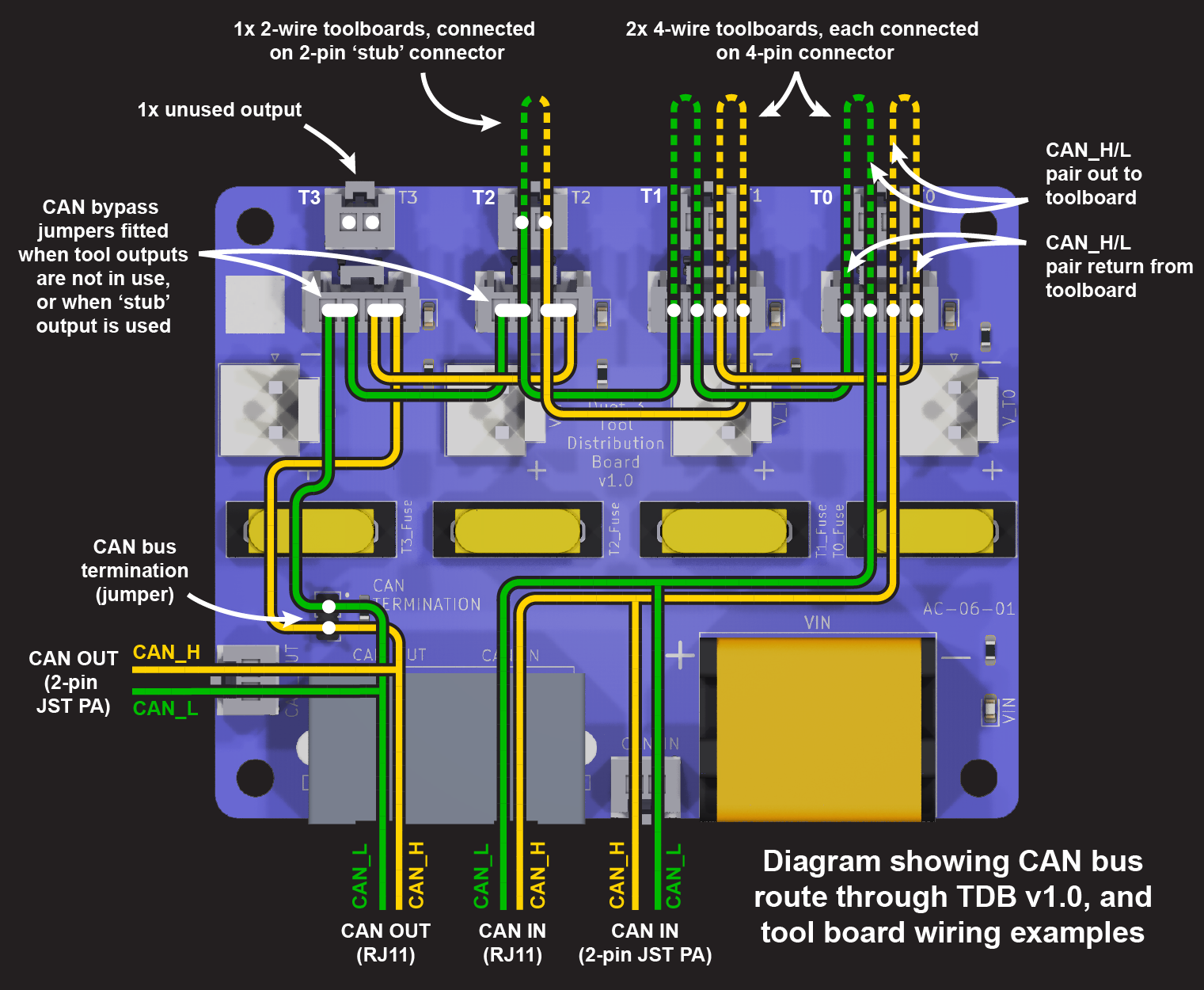
Wiring diagram
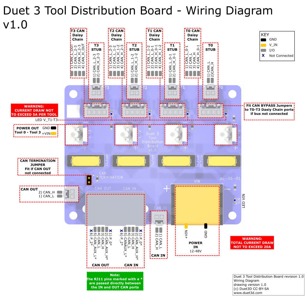
Power distribution
CAN Wiring
Tool Distribution Board provides ample flexibility in CAN bus extension, allowing several ways to connect expansion boards and tool boards with two-wire or four-wire CAN bus. Tool Distribution Board accomplishes this function by extending the CAN bus internally.
Connecting expansion boards and tool boards
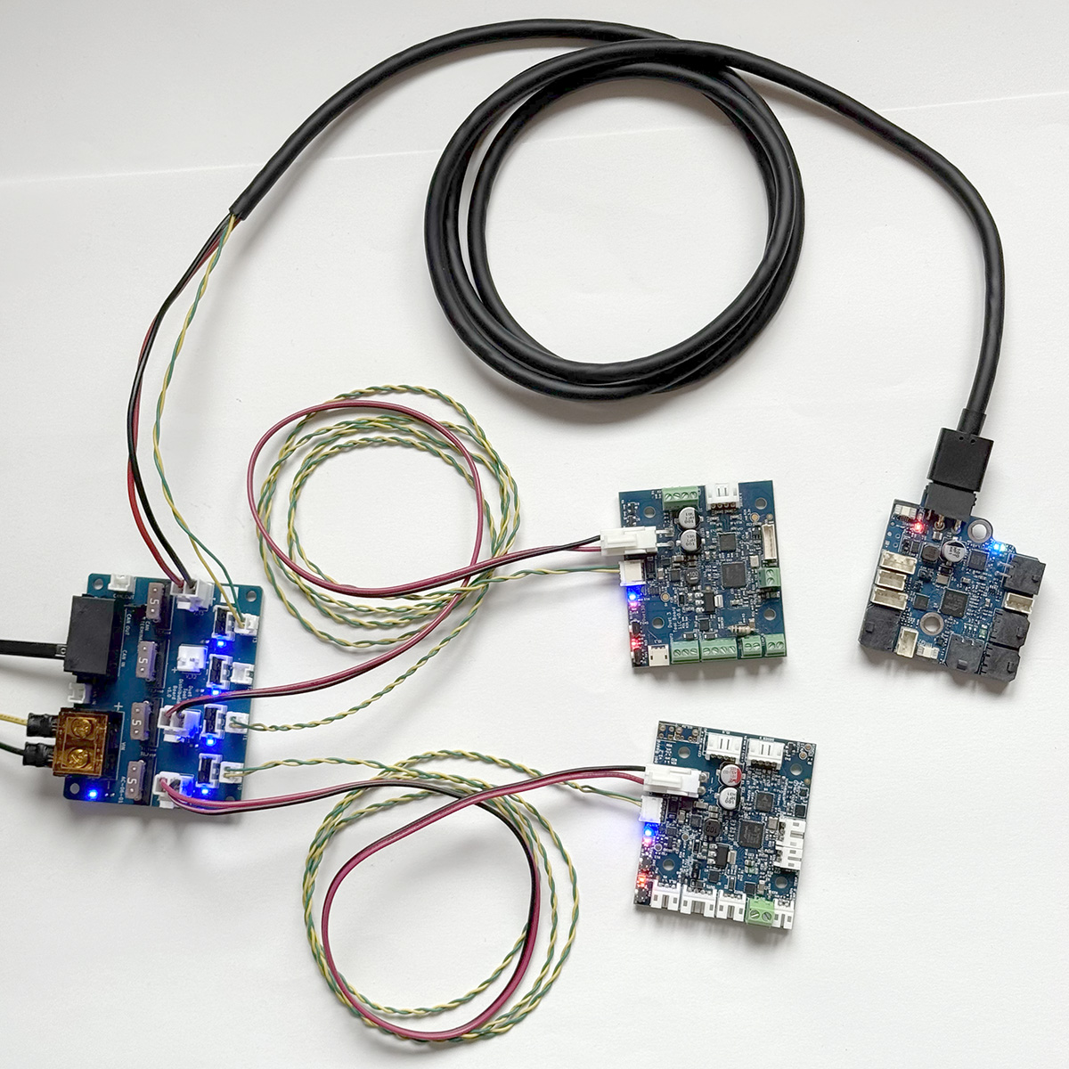
Tool Distribution Board offers practical connection points for connecting either a loop in the CAN bus (4-wire connection) or a branch (stub) (2-wire connection). The two connection types can be freely combined as long as CAN bus continuity is maintained.
4-wire connection
Expansion boards and tool boards that have two CAN pin pairs or two RJ11 ports can be looped onto the CAN bus. These include Duet 3 1LC, 3HC, 1XD, 1HCL and M23CL.
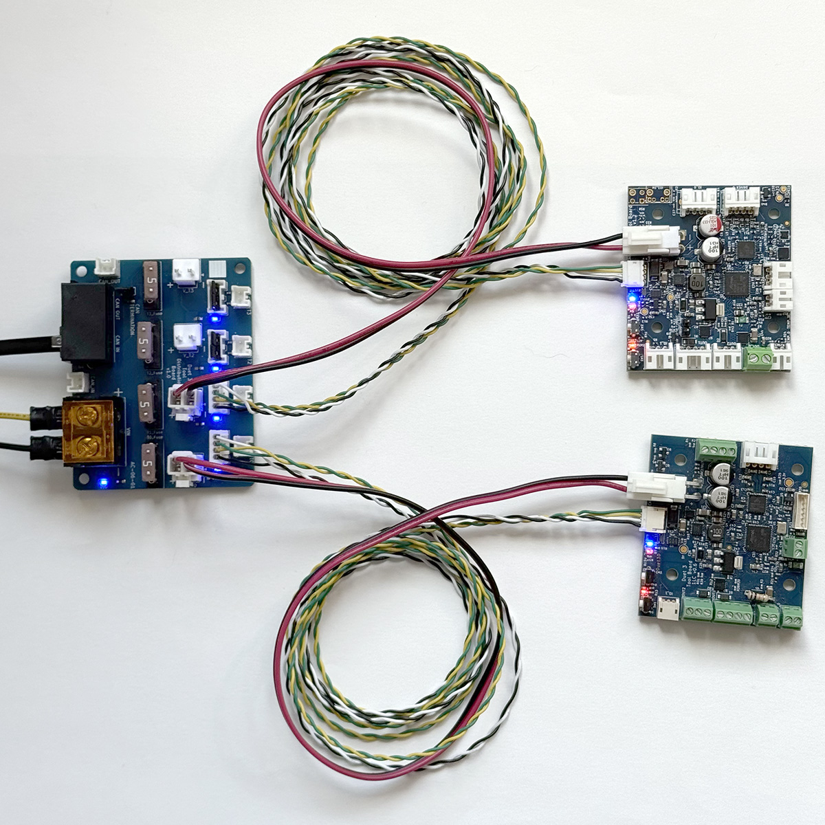
Tool Distribution Board was originally developed to simplify the connection of Duet 3 Toolboards 1LC.
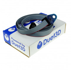
Crimps and connectors for making cables are provided.
Connection procedure:
Since Tool Distribution Board simply provides a convenient connection point to create a loop in the CAN bus, multiple boards can be connected within each loop starting from the board itself.
Connection procedure:
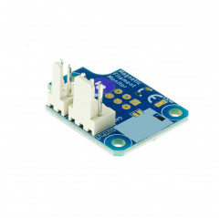
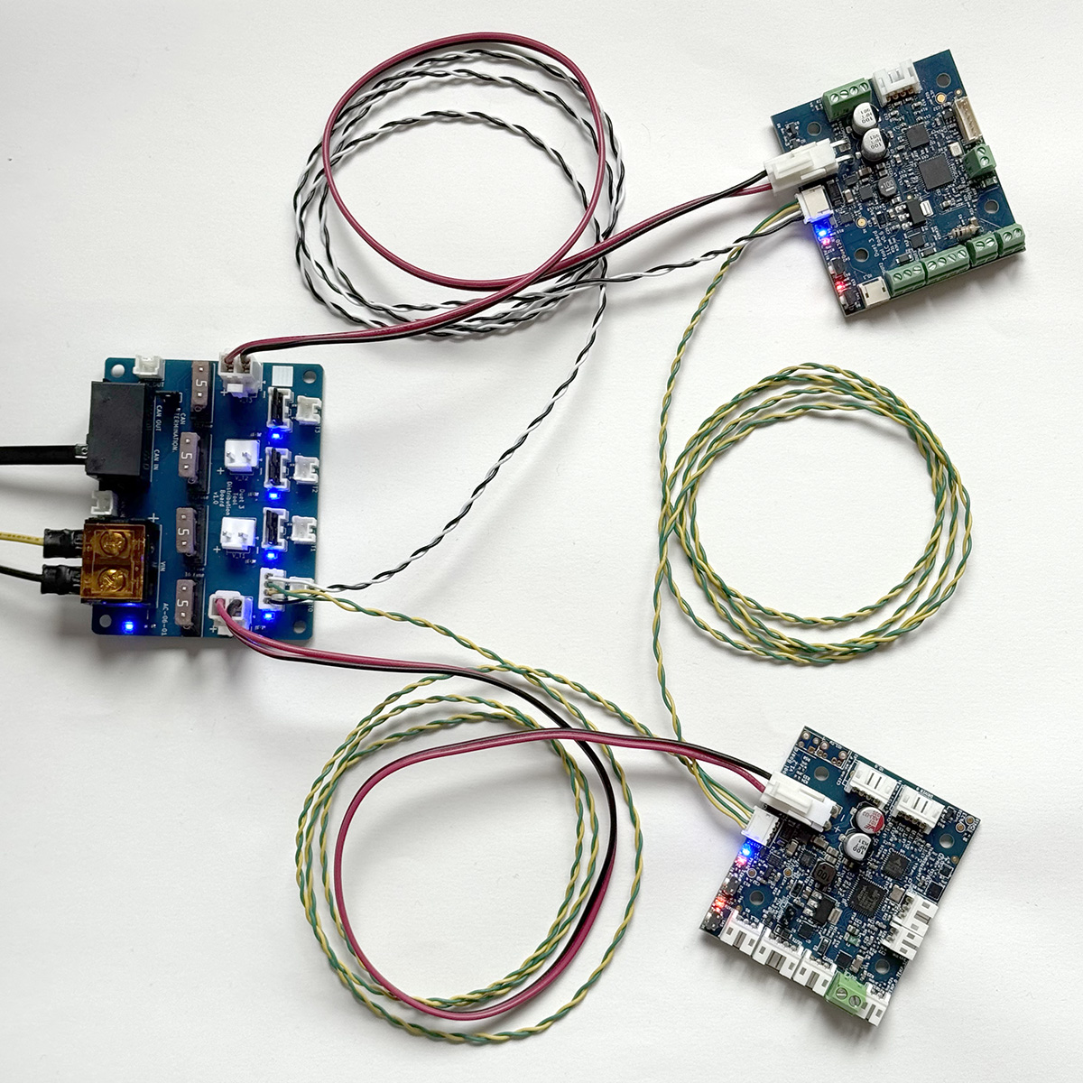
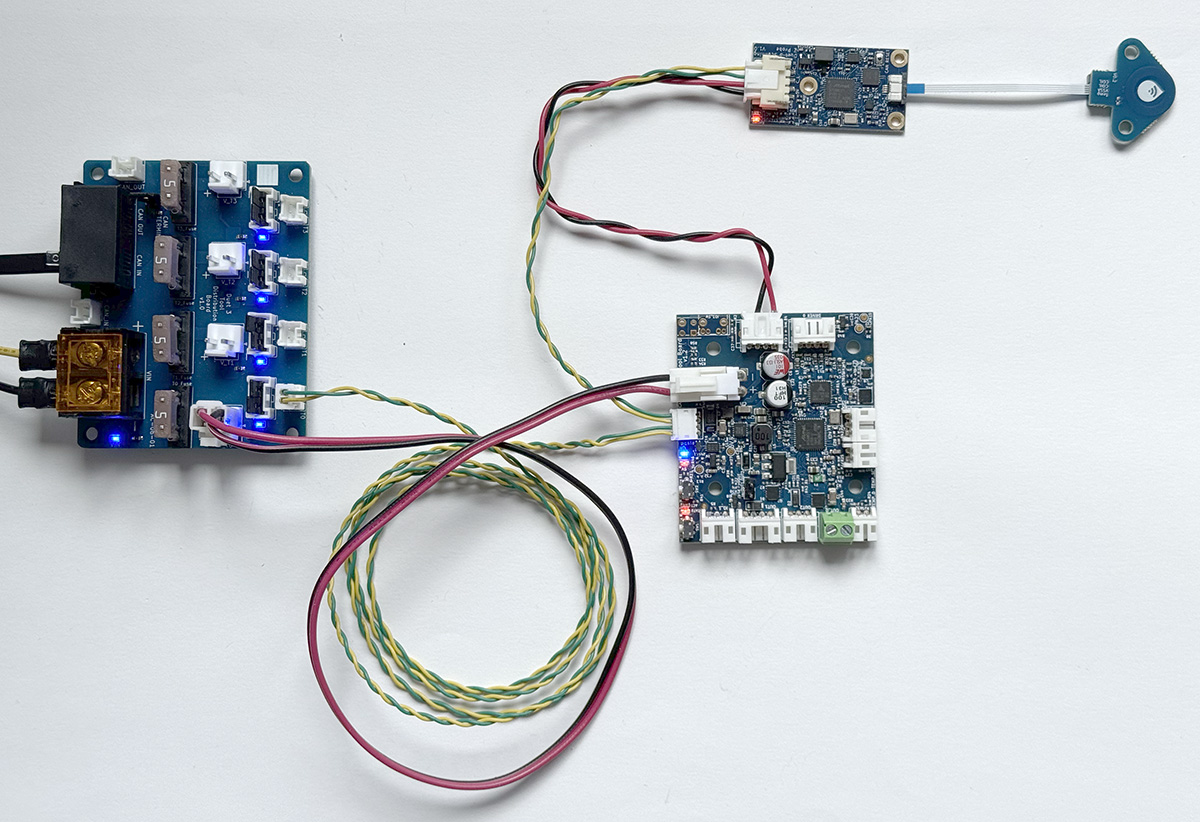
Boards that have only a 2-pin connection (e.g., Duet 3 Roto Toolboard, Scanning Z Probe, and main boards used as expansion boards) can still use a 4-wire connection by making a loop of CAN wires with a short ("stub") 2-wire branch connected to the board.
2-wire connection
Some expansion boards and tool boards have only a 2-pin CAN connection, for example, the Duet 3 Roto Toolboard, the Scanning Z Probe, and main boards used as expansion boards. This requires a 2-wire connection. Actually, all expansion boards, tool boards and main boards (used as expansions) can be connected using only two CAN wires. This type of connection functions as a branch from the main CAN bus, called a "stub."
Rules for "stub" connections
Procedure for connecting a stub to the Tool Distribution Board.
Stubs can support more than one board as long as the total stub length is less than 1 meter.
Unused Tool Connections
If no expansion board or tool board is to be connected to a Tool connector, leave the CAN bypass jumpers on.
This allows the CAN bus to continue to the next Tool connector, up to the termination jumper or RJ11 CAN OUT connector.
Termination
It is necessary to provide CAN bus termination at both ends of the bus. The main board (mainboard), usually located at one end, provides termination at that end. As long as bus continuity is maintained through the Tool Distribution Board (i.e., with bypass jumpers engaged or 4-wire connection to the expansion/tool boards), the CAN bus can be terminated directly at the Tool Distribution Board.
Alternatively, termination can be applied to the last tool board connected to the Tool Distribution Board.
If there are additional CAN expansion boards connected via the RJ11 CAN OUT connector, remove the termination jumper from the Tool Distribution Board.
Package contains: 1 x Duet 3 Tool Distribution Board v1.0 - expansion for Duet 3 via CAN-FD bus