Worldwide express shipping
Worldwide express shipping

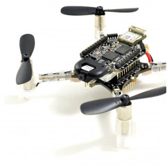
Light up the dark with custom patterns using the LED-ring expansion board for Crazyflie 2.X. Equipped with 12 powerful downward-facing RGB LEDs, you can create custom patterns via firmware and control them from your Android/iPhone device or computer. Two additional front LEDs, which are also very powerful and can be turned on or off, act as spotlights.
NOTE: This deck is not compatible by default with the Crazyflie 2.1 Brushless. A software modification must be made to use it.
Features
Different LED patterns can be selected from the Flight tab of the CFclient.
Once the desired pattern is chosen, you are ready to take off!
Firmware implementation.
All LED-ring deck effects are implemented in driver led-ring.
Hardware Hack: LED-ring on top
If you want to place the LED-ring on top of the Crazyflie in combination with the Flow deck V2, here is what you need:
Basically, what we do is flip the pin layout of the LED deck so that it is compatible to be mounted on top of the Crazyflie.
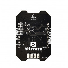
The picture below shows how to solder the connections: GND (ground), IO2, OW (1-wire deck memory) and VCOM (power supply).
See the dedicated page to familiarize yourself with the pinout of the expansion decks.
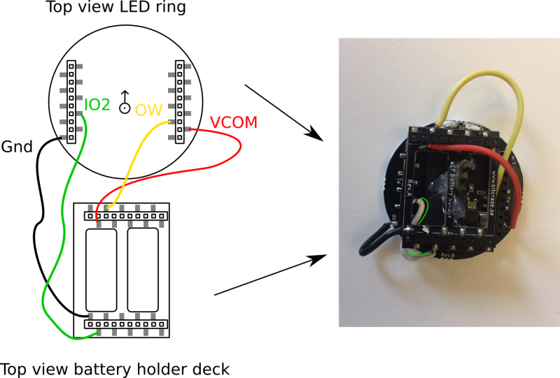
IO3 was not connected on purpose, as the Flow deck V2 is already using this pin; otherwise the LED deck and Flow deck V2 would conflict in communication with the Crazyflie. However, the LED deck works even without connecting IO3.
The battery holder deck can be glued onto the LED deck or secured with tape. The soldering and wiring shown is a bit crude to clearly show how to do it; if you want tidier wiring, just use thinner wires and some dexterity with soldering.
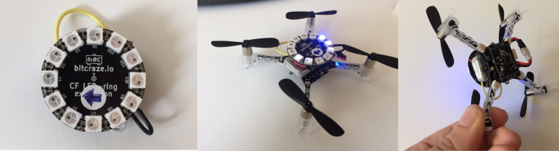
Pay attention to the orientation of the LED deck, which has now changed. The battery holder is put to the side to avoid shorting with the LED deck, but now you need to point to the new "front" of the LED deck. In the bottom left photo it is shown with a sticker.
The last step is to modify the firmware. The GPIO pins used by a deck are recorded in driver of the deck to enable the system to detect any conflicts. Since the LED-ring does not use IO3 in this configuration, it is necessary to remove IO3 from driver of the deck in order to use it in conjunction with the Flow deck (which uses IO3).
Open the ledring12.c file and edit the corresponding line in driver of the deck by removing | DECK_USING_IO_3.
Recompile the firmware and flash it to the Crazyflie.
Deck LED has been tested, converted together with Flow deck V2 using CFclient and you continue to receive values and parameters correctly from both decks driver.
The package contains: 1 x LED-ring deck - Bitcraze