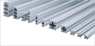
Workflow for designing an automation frame
Operational steps
• Step 1: Define the cell volume and required free spaces
• Step 2: Identify loads (machinery weight, dynamic forces from robots/conveyors)
• Step 3: Choose the profile slot suited to load and aesthetics
• Step 4: Design the frame respecting bracing rules
• Step 5: Define brackets, plates and accessories
• Step 6: Verify stiffness and natural frequencies (if dynamic)
• Step 7: Add finishes (covers, doors, panels)
Static vs dynamic loads
Static loads
These are constant loads: machinery weight, fixed equipment, hanging cabling. Sizing is straightforward, with safety coefficient typically 2-3 over the design load. For an aluminium frame, slot-8 30×30 profile handles vertical loads up to about 1000-1500 N per upright on a 1 m free length.
Dynamic loads
These are variable loads: robots in motion, conveyors with stop-and-go, vibrations from operating motors. They generate inertial forces several times higher than the apparent weight. For a 10 kg payload SCARA at 1 m/s acceleration, peak forces on the frame easily reach 200-500 N per anchor point.
Vibrations and natural frequency
Each frame has natural frequencies that must not coincide with the operating excitation frequencies of the machines (typically 5-50 Hz for industrial robots). Resonance amplifies vibrations and reduces working precision. A higher first natural frequency means stiffer frame, achieved by increasing section, reducing free lengths or adding diagonal bracing.
Slot selection by automation type
|
Application |
Recommended slot |
Notes |
|
Light/assembly cell |
Slot 6 (30×30) |
Operator weight, no dynamics |
|
SCARA robot cell |
Slot 8 (40×40) |
Vertical load + moderate dynamics |
|
Articulated robot cell |
Slot 10 (45×45) |
Significant dynamic loads |
|
Conveyor structure |
Slot 8 (40×40 to 80×40) |
Distributed load, modular structure |
|
Safety enclosure |
Slot 6 (30×30) |
Only own weight + panels |
Connections: brackets and plates
Standard brackets
Reinforced corner brackets are the most common solution for 90° connections. Stiffness depends on bracket size and number of fastening screws. For a 30×30 profile, a 30×30 bracket with two M6 screws guarantees adequate stiffness in most automation applications.
Inner plates
For high-stiffness connections (vibrating frames, dynamic loads), use inner plates instead of external brackets. Connection is hidden inside the slot, with screw passing transversely. Aesthetically cleaner and higher torsional stiffness.
Custom plates
For special node connections (multiple intersections, frame-to-base joints), CNC-milled aluminium plates are designed on drawing. Typical materials 6082 anodised or ground 5083 for high-precision applications.
Accessories that complete the frame
Adjustable feet
They support the frame and enable height adjustment to compensate for floor unevenness. For an automation cell, choose feet with M12 or M16 threaded base and conservative load capacity (factor 2-3 safety over real weight). Anti-vibration models include a rubber buffer that filters vertical vibrations.
End caps and slot covers
End caps close profile ends. Slot covers fill empty slots, preventing dirt accumulation and improving aesthetics. Both available in PVC or PA, in colours matching the standard profile finish.
Doors and panels
For safety enclosures, sliding or hinged doors are typically built with the same profile system, with polycarbonate panels or shaped sheet. Sliding rails and hinges are standardised on the slot.
Stiffness verification
Rule of thumb
For an automation frame, a useful rule is keeping the deflection of each free upright under 1/500 of the free length under maximum dynamic load. For a 1 m upright, this means maximum deflection of 2 mm.
Free length
Free length is the distance between two consecutive constraint points (bracket, bracing). Reducing free length is the most effective way to increase frame stiffness without increasing the section. A diagonal bracing typically halves the deflection of an upright.
Practical verification
For preliminary verification, structural design tables from profile manufacturers can be used. For complete dynamic verification, an FEM analysis is needed, especially for robot cells with multi-axis movements.
Case study: frame for SCARA robot cell
An end-of-line cell integrator was designing a frame for a SCARA robot with 5 kg payload, 0.5 m/s² acceleration, working at 1 cycle/second. Initial design used 30×30 slot-6 profiles for the entire frame, with standard external brackets. During pre-production testing, the robot tower showed visible vibrations affecting placement repeatability. The fix involved replacing the tower with 40×40 slot-8 profiles, adding diagonal bracing on the bottom and using inner plates instead of external brackets. Effect on repeatability was immediate.
Common mistakes in automation frame design
• Choosing the slot only based on apparent weight, ignoring dynamics
• Overlong free lengths without bracing
• Brackets undersized for the loads
• Ignoring own-weight deflection in long frames
• Failing to verify natural frequencies vs robot operating frequencies
• Inadequate feet anchoring with respect to total weight
• Mixing different slots in the same frame, complicating accessories
Quick sizing rules
For an automation cell
• Static load < 500 N per upright: slot 6 (30×30)
• Dynamic load < 1000 N: slot 8 (40×40)
• Significant dynamic load (heavy robots): slot 10 (45×45)
• Free length > 1.5 m: add diagonal bracing
• Frequencies > 50 Hz: FEM analysis recommended
FAQ
Which slot to use for a robot cell?
For a SCARA robot, slot 8 (40×40) is the typical baseline. For heavier articulated robots, slot 10 (45×45) is preferred. Selection depends on payload, accelerations and free lengths.
How to fix the frame to the floor?
Use adjustable feet with M12 or M16 base, sized with safety factor 2-3 on total weight. For dynamic cells, prefer anti-vibration feet with rubber buffer. For permanent installations, expansion anchor fastening to floor.
Do I need FEM analysis for an aluminium frame?
Not always. For static frames with moderate loads, sizing tables suffice. For dynamic cells with robots, conveyors or sensitive equipment, FEM analysis is recommended to verify natural frequencies and deflections.
Can I extend a frame after installation?
Yes, this is one of the advantages of modular aluminium frames. Profiles can be added by widening the structure, with appropriate brackets. Verify that the new configuration does not introduce critical free lengths.
How are panels attached to the frame?
For polycarbonate panels or sheet, dedicated profiled gaskets are used and slide into the slot. The panel slides into the gasket and is held in place by the profile geometry. For removable panels, latches or hinges are added.
Conclusion
Designing an aluminium frame for automation is not just sizing the section. It requires considering static and dynamic loads, choosing the right slot, providing adequate connections and verifying overall stiffness. The flexibility of t-slot aluminium systems makes them ideal for automation, but the apparent simplicity hides design traps.